
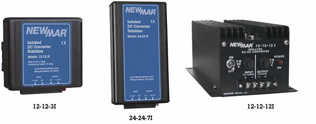
12 & 24 Volt Stabilizing Converters
Feed sensitive electronics with proper voltage regardless of battery condition. These stabilizing converters provide continuous, precisely regulated output over the entire range of a battery’s usable voltage. This prevents subjecting loads to fluctuating input voltage which can cause shutdown, diminish performance and possibly damage sensitive circuitry.
These converters provide total input/output isolation, virtually eliminating conducted line noise and permitting connection of negative ground gear to positive or floating ground systems, or vice versa. They can be modified for use as battery chargers, allowing them to maintain a battery at a great distance from the primary voltage source, providing reserve power if the main source fails. The rugged anodized aluminum case is ideal for marine applications.
Application Benefits Include
- Operate electronics at optimal input voltage, even from nearly drained batteries
- Boost voltage to compensate for voltage drops in long wire runs from batteries
- Eliminate voltage drops during momentary high current drain from batteries, as during engine start
- Eliminate voltage fluctuation from charge sources
- Eliminate voltage overshoot due to sudden removal of high current load

| Model | Input voltage |
Input Amps |
Output voltage |
Output Amps | Case Size |
Weight | ||
|---|---|---|---|---|---|---|---|---|
| Intermittent | Continuous | Lbs | Kg | |||||
| 12-12-3i | 10-16** | 4 | 13.6 | 3 | 3 | C-1 | 1 | .45 |
| 12-12-6i | 10-16** | 8 | 13.6 | 6 | 6 | C-2 | 2 | .9 |
| 12-12-12I | 10-16** | 19.2 | 13.6 | 12 | 8 | C-3 | 6 | 2.7 |
| 12-12-35I | 10-16** | 56 | 13.6 | 35 | 20 | C-6 | 12 | 5.5 |
| 24-24-3i | 20-32 | 3.7 | 27.2 | 3 | 3 | C-1 | 1 | .45 |
| 24-24-7i | 20-32 | 8.7 | 27.2 | 7 | 7 | C-2 | 2 | .9 |
| 48-24-3I | 20-56 | 4.8 | 24.5 | 3 | 3 | C-7 | 7 | 2.7 |
| 48-24-6I | 20-56 | 9.6 | 24.5 | 6 | 4 | C-1 | 6 | 2.7 |
| 48-24-9I | 20-56 | 14.4 | 24.5 | 9 | 5 | C-1 | 8 | 3.6 |
| 48-24-18I | 20-56 | 28 | 24.5 | 18 | 10 | C-6 | 12 | 5.5 |
| **11.5 VDC minimum start-up voltage, then operates @ 10-16 VDC from 1 amp minimum to full load | ||||||||
Case Size
| Case | inches | Centimeters | ||||
|---|---|---|---|---|---|---|
| H | W | D | H | W | D | |
| C-1 | 3.5 | 3.5 | 1.75 | 8.9 | 8.9 | 4.5 |
| C-2 | 6.5 | 4.0 | 1.75 | 6.8 | 10.2 | 4.5 |
| C-3 | 4.25 | 5.9 | 14.0 | 10.8 | 15.0 | 35.6 |
| C-4 | 6.0 | 4.7 | 14.0 | 15.2 | 11.9 | 35.6 |
| C-5 | 6.0 | 4.7 | 16.0 | 15.2 | 11.9 | 40.6 |
| C-6 | 6.0 | 6.8 | 16.5 | 15.2 | 17.3 | 41.9 |
| C-7 | 2.8 | 4.2 | 10.4 | 7.1 | 10.7 | 26.4 |
| C-8 | 3.5 | 3.5 | 1.75 | 8.9 | 8.9 | 4.5 |
Specifications
Output: 12 or 24V, nominal, see matrix
Ripple: 150 mV P-P maximum
Regulation: 1% Line/Load
Duty Cycle Ratings
Intermittent – 20 minutes max on time, 20% duty. Current limit set at approx. 105% of intermittent rating.
Continuous – 24 hours, 100% duty
Idle Current: Less than 100 mA (including power “ON” light )
Operating Temp: 0-50° C, Derate Linearly From 100% @ 40° C To 50% @ 50° C. Thermal shutdown @ 70° C Case Temperature.
Switching Frequency: 40 Khz.
Efficiency: 85% – Typical.
Isolation – Output/Chassis; Input/chassis: 250 VDC
Mechanical
- Anodized aluminum heat sink case
- Front panel terminal block
- Heavy duty mounting flange
- Conformal coated PC board
Options/Factory Modifications
- Operation as a battery charger (contact factory)
- Parallel/redundant operation (contact factory)
- High vibration mounting kit
- Non-standard output voltage (contact factory)
Option: Extreme Vibration Mounting Kit
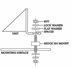
The Extreme Vibration Mounting Kit is available to protect NEWMAR power converters from the extreme stresses of shock and vibration when mounted on high vibration vehicles.
The kit (pictured here) replaces the standard vibration kit provided with the unit and fits into the unit’s mounting flange to act as a “super shock absorber” for electronics in high vibration applications. It is available to fit all NEWMAR units from 2 to 70 lbs. Specify KIT–L for units which weigh 2–15 lbs. and Kit–H for units which weigh 16-70 lbs.